Inductors
An inductor is a passive electrical component that opposes sudden changes in current even if the voltage across it changes suddenly. Unlike resistors where the current changes instantaneously with voltage, inductors take time to build the current. Inductors are also known as coils or chokes.
The fundamental relationship between current and voltage of an inductor is :
$$v=-L\cfrac{di}{dt}$$
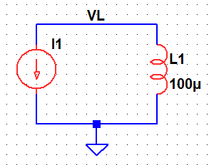
Circuit symbol of an inductor

In circuit diagrams, inductors are represented using symbols that resemble coiled wires. The symbol typically includes the label "L" to represent inductance.
What is inductance?
Inductance (L) is the property of an inductor that quantifies its ability to store energy in a magnetic field. It is measured in henrys (H). The inductance is directly proportional to the number of turns in the coil and the cross-sectional area enclosed by the coil.
Inductive reactance
When a DC voltage is applied across an inductor, the current is infinite. However, when an alternating current (AC) flows through an inductor, the changing voltage causes the magnetic field to change. This does not allow the current to build up quickly. This effect is called inductive reactance (XL). Inductive reactance is proportional to both the frequency of the AC signal (f) and the inductance (L) and is given by the formula :
$$X_L=\omega{}L=2\pi{}fL$$
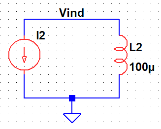
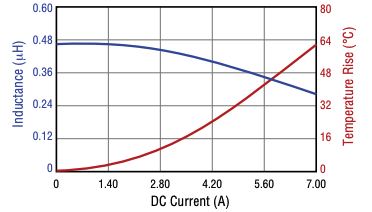
For a fixed inductance, the voltage across the inductor rises with input current's frequency, which is indicated in the above graph.
Self and mutual inductance
Self-inductance is the property of a single coil or inductor by which a changing current within creates its own magnetic field which induces an electromotive force (EMF) in the same coil. The self-inductance (L) depends on the number of turns, coil area, core material, and coil length.
$$V=-\underbrace{\left(\cfrac{\mu_oNA}{l}\right)}_{L}\cfrac{di}{dt}$$
Mutual inductance, on the other hand, occurs when the magnetic field produced by one coil affects another nearby coil and induces an EMF in it. This happens in devices like transformers, where energy is transferred between coils through a shared magnetic field. The amount of induced voltage depends on the rate of current change in the primary coil and the degree of magnetic coupling between the two coils.
More about self and mutual inductance : Self and Mutual inductance
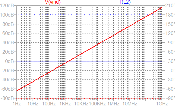
Inductor parameters and characteristics
A real-world inductor contains parasitic components that restrict its ideal performance. It can be represented by the equivalent model shown below:
The DC resistance (DCR)
The DC resistance represents the resistance of the wire used in the winding. Although inductors ideally resist only changes in current, real conductors have resistance that causes power losses (I²R) and affects efficiency. Low DCR is desirable, especially in power applications, to minimize heating and voltage drop.
Quality factor
Real inductors have turn-to-turn winding parasitic-capacitance (Cp) that acts as if it were a parallel circuit element. We can treat an inductor as a parallel combination of DCR resistance (Rdcr), Cp and L. A higher Q (quality-factor) indicates lower energy losses through Rdcr and better performance in resonant circuits.
Self Resonant Frequency (SRF)
Impedance magnitude increases with frequency as expected up to the self-resonant frequency (SRF). At SRF, the impedance of an inductor is at its maximum value due to self-resonance with the parasitic capacitor (Cp). Beyond SRF frequencies, impedance decreases because parasitic capacitive (Cp) behavior dominates.
Core saturation
Ideally, the inductance value should remain constant with the current flowing though it. However, in reality, the inductance drops with high current. This phenomena is called core saturation. Core saturation occurs when the magnetic material reaches its flux limit. With increase in temperature, the core-saturation happens earlier.
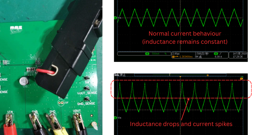
$$\Delta{}I=\cfrac{(V_{in}-V_o)\Delta{t}}{L}$$
\(\Delta{}t\) is the time duration for which input voltage is applied across the inductor in DC-DC converters. We can see from the relationship of current through the inductor that the current increases as the inductance decreases. This is exactly what is shown in the figure above.
Current rating
The current rating indicates the maximum continuous current the inductor can handle without excessive heating or core saturation. RMS rated current (Irms) causes a specific temperature rise (~40°C) above the ambient temperature. This temperature increase is caused by RDCR. The saturation current limit (Isat) defines the inductance value drop (by ~30%). The peak inductor current should be below the saturation current limit.
Behaviour in AC and DC circuits
Phase relationship between voltage and current
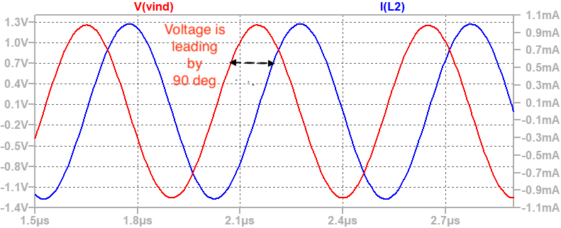
If a sinusoidal current input is applied, we can observe that the voltage developed is leading the current by 90°.
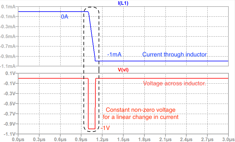
Transient response of inductors
The voltage across an inductor is proportional to the rate of change of current according to \(V=-L(di/dt)\). When the current remains constant, the voltage across the inductor is zero. As shown in the figure below, when the current changes from 0 mA to –1 mA, the inductor develops a non-zero constant voltage (-1V) during that transition. Conversely, when a fixed voltage is applied across an inductor, the current through the inductor rises linearly over time.
Energy stored in inductor
An inductor stores energy in the form of a magnetic field when current flows through it. Unlike resistors, which dissipate energy as heat, inductors temporarily store electrical energy and release it when the current decreases. This energy storage and release behavior makes inductors crucial in applications such as DC-DC switching regulators, and energy harvesting systems, where controlled transfer of magnetic energy ensures stable and efficient circuit operation.
When a current flows through the coil of an inductor, a magnetic field is established around it. As the current increases, energy is gradually stored in this magnetic field. The amount of energy (W) stored in an inductor is given by the formula:
$$E=\cfrac{1}{2}Li^2$$
where L is the inductance in henries (H), and i is the current in amperes (A). This equation shows that the stored energy depends on both the inductance and the square of the current.
Series and Parallel combination of inductors
Series combination
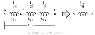
When inductors are connected in series, the total inductance is the sum of all individual inductances, assuming negligible mutual coupling between them. Mathematically, it is given by:
$$L=L_1+L_2+\dots{}+L_n$$
Parallel combination

When inductors are connected in parallel, the total inductance is reduced, and it is calculated using the reciprocal formula:
$$\cfrac{1}{L}=\cfrac{1}{L_1}+\cfrac{1}{L_2}+\dots{}+\cfrac{1}{L_n}$$
More about series and parallel combination of inductors
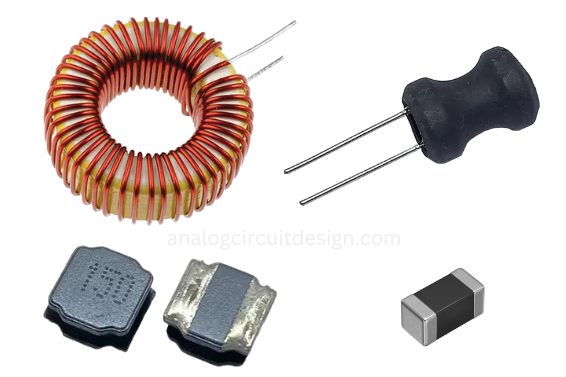
Construction of an inductor
An inductor typically consists of a coil of wire wound around a core, which is often made of materials with high magnetic permeability, such as iron. The coil's inductance is determined by factors like the number of turns in the wire, the coil's geometry, and the core material.
Winding technique
The winding technique also plays a critical role in determining the inductance. Tightly wound coils with many turns increase the magnetic field strength and inductance, while spacing between turns can reduce parasitic capacitance, improving high-frequency performance. Toroidal windings, where the coil is wound around a closed-loop core, minimize magnetic losses and external interference.
Winding core material
The energy storage occurs in the core, which can be made of different materials such as air, ferrite, or iron powder. The choice of core material significantly influences the inductance value and efficiency. For example, air-core inductors are linear and ideal for high-frequency applications, while ferrite and iron powder cores enhance magnetic coupling and energy density in power circuits.
Applications
Inductors slow down current surges or spikes by temporarily storing energy in an electromagnetic field and then releasing it back into the circuit. Some applications are:
- Filtering: They are used in combination with capacitors to create low-pass, high-pass, band-pass, or band-stop filters.
- Energy Storage: Inductors can store energy in magnetic fields and release it when the current changes.
- Transformers: They are a key component in electrical transformers, which transfer energy between circuits through electromagnetic induction.
- Solenoids and motors: Devices such as motors and solenoids use inductors to convert electrical energy into mechanical motion.